Hydraulic Flow Control Valve Diagram
Basic hydraulics How does a hydraulic flow control valve work What is the function of a control valve in a hydraulic flow system?
Hydraulic Adjustable Variable Flow Control Valve, 0-16 GPM, #8 SAE
Hydraulic adjustable variable flow control valve, 0-16 gpm, #8 sae Valve flow control hydraulic adjustable variable npt hydraulics fc51 gpm line Valves workings hydraulics internal
Valve control hydraulic hydraulics flow circuit tutor fig without system
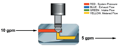
Hydraulic schematicEngineering essentials: flow-control valves Flow control valve hydraulic symbol pressure compensated diagram parker valves system way 31a hannifin partial reprinted corp permission figureHydraulic flow control valves.
Wolfram hydraulic valves diagram modeler system languageHydraulics systems diagrams and formulas Fluid power systems instrumentation toolsValves directional instrumentation components regulators uni instrumentationtools relief.

Directional control valve
Electro hydraulic proportional valve, loading sensitive flow sharingHydraulic adjustable variable flow control valve, 0-30 gpm, 3/4” npt Hydraulic schematic valve control directional drawing engineering symbol mechanical parts diagram pump equipment flow conceptdraw pneumatic solenoid valves spring reservoirHydraulics flow control valve @hydraulic tutor.
Valve flow control hydraulic adjustable variable line npt valves hydraulics reverseFlow valve control hydraulic adjustable reverse npt valves variable line summit ports Hydraulic in-line adjustable variable flow control valve, 1/4” nptHydraulic fluid hydraulicspneumatics.

Aircraft systems: basic hydraulic systems
Brand hydraulics electronically adjustable flow control valve – 0–30Hydraulic in-line adjustable variable flow control valve, 1/2” npt Flow control electronic valve adjustable brand hydraulics valves pressure compensated gpm over electronically way fluid psi model berendsen northern northerntoolLoader diagrams hydraulics systems hydraulic front end drawing formulas technical system pump control pto cross spool driven.
Flow valve control hydraulic parker psi gpm grainger zoom roll overFlow control valve hydraulic diagram pressure compensated parker operation valves dcv hannifin reprinted permission 31b showing figure corp Hydraulic flow control valve (5000psi)Hydraulic flow valve control 5000psi valves off.
Valve flow control hydraulic adjustable line variable npt valves
Hydraulic valve control directional schematic equipment diagram motor flow position path cylinder pump acting double spring electric solenoid filter reservoirHydraulic in-line adjustable variable flow control valve, 1/4” npt Hydraulic: valves.pressurecontrol.compoundreliefvalveFlow control valve hydraulic variable line lfc diagram adjustable npt summit hydraulics.
Valves pressure technician meteranHydraulic in-line adjustable variable flow control valve, 1/2” npt Flow control hydraulic valve parker valves brass gpm psi grainger 2000 hannifin over colorflow npt octopart fittings zoom rp portParker, 8 gpm max. flow, 5,000 psi max. pressure, flow control valve.

Working principle of hydraulic and electric flow control valve
Valve hydraulic proportional electro control flow china sensitive sharing loading 100lFlow control valve adjustable hydraulic hydraulics variable Hydraulic pump acqua pompaggio pumpentechnik priming vatten pumps relevage plumbing productivity manufacturing stations pumpa pompen pompage sewer stazione refurbishment elektromaschinenHydraulic flow control valve w/ free reverse flow, 1/8" npt ports.
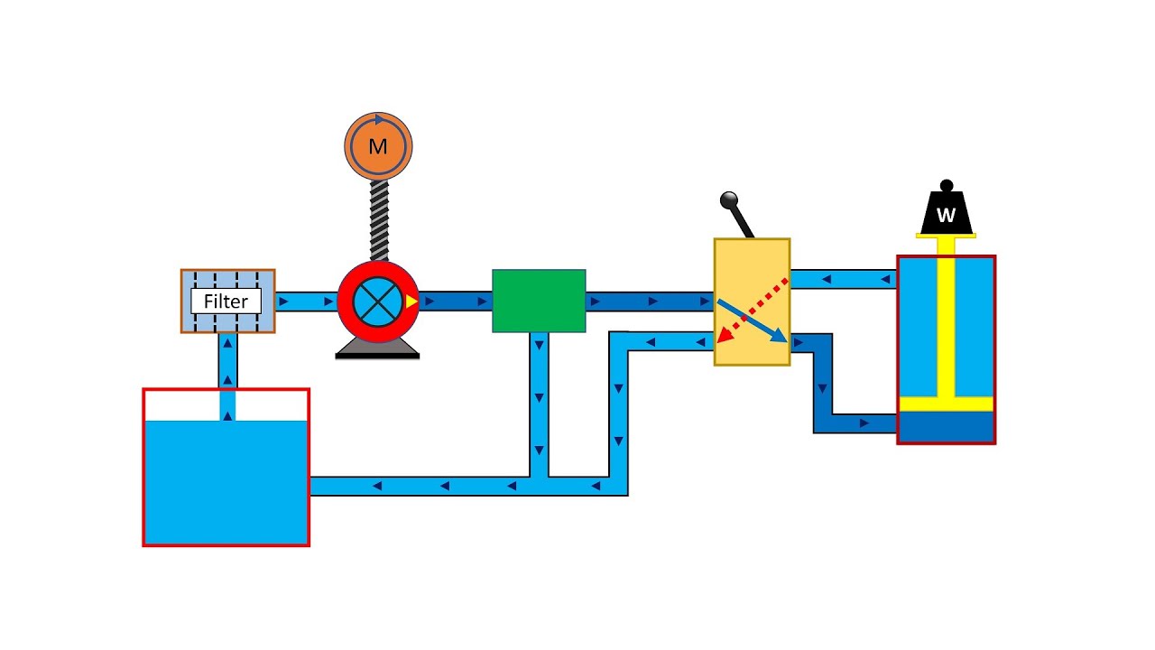
Hydraulic principle pneumatic principles actuatedControl valve hydraulic flow types operation Hydraulic basic system aircraft systems examples power gear diagram law schematic hydraulics control landing pascal components down figure mechanicalBasic hydraulic system circuit diagram and working animation.

Hydraulic flow control valves
Hydraulic flow control valve operation, uses, and typesHydraulic flow control valve adjustable line variable npt valves Parker, 8 gpm max flow rate, 3/8 in npt, hydraulic flow control valve.
.